
The latest release of Java ME 8 includes a powerful API for controlling devices such as LEDs, relays, LCDs, sensors, motors, and switches.
This article is the first in a three-part series about how to connect electronic sensors to the Raspberry Pi Model B using general-purpose input/output (GPIO), inter-integrated circuit bus (I2C), serial peripheral interface bus (SPI), or universal asynchronous receiver/transmitter (UART) interfaces.
By using Java ME 8 to control devices with different types of interfaces and connecting the devices to a Raspberry Pi, we can create an Internet of Things (IoT) world.
This article focuses on using GPIO and shows examples of how to develop classes in Java ME 8 that can
- Detect a flame using a DFRobot flame sensor (model DFR0076)
- Detect movement using an HC-SR501 passive infrared (PIR) motion detector
- Measure distance using an HC-SR04 ultrasonic ranging module
Note: The complete example code for this NetBeans IDE 8.0 project can be downloaded here.
Device I/O API
The Device I/O API specification defines a generic peripheral device I/O API for Java applications running on small embedded devices. It defines APIs for some of the most common peripheral devices, including the following:
- GPIO devices
- I2C devices
- SPI devices
- Analog-to-digital converters (ADCs)
- Digital-to-analog converters (DACs)
- UART devices
- Memory-mapped I/O (MMIO) devices
- AT command devices
- Watchdog timers
- Pulse counters
- Pulse-width modulation (PWM) generators
- Generic devices
Circuits We Will Create
A GPIO device can be used as either a digital input or a digital output, it can be disabled or enabled, and it can be used to drive "interrupt" lines. However, a very important consideration is that all Raspberry Pi GPIO pins operate at 3.3 V. Therefore, it is very important to check the technical specifications of the devices you want connect to determine if they are using 3.3 V or 5 V. In some cases, you will need to use a logic level converter such as this.
Based on the block diagram shown in Figure 1 and the components shown Figure 2, we create the circuits shown in Figure 3.
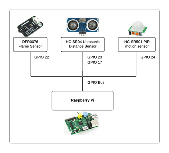
Figure 1. Block diagram of the circuits we will create
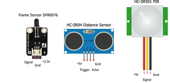
Figure 2. Components we will use
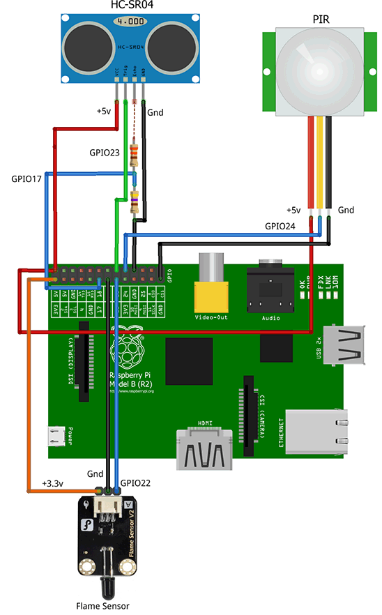
Figure 3. Schematic of the circuits we will create
Connecting the Flame Detector
The DFR0076 flame sensor from DFRobot can be used to detect fire or other wavelengths of light between approximately 760 nm and 1100 nm. We can connect it to 3.3 V or 5 V, and the detection range is approximately 20 cm (4.8 V) to 100 cm (1 V). When fire is detected, it pulls up the signal pin.
Let's connect the flame sensor to the Raspberry Pi's 3.3 V, Gnd, and GPIO 22 pins, as shown in Figure 3, and create a Java ME 8 class for the flame detector sensor control.
First, create a class
DFR0076Device that uses the Device Access API, and define a variable pin that supports the interface to GPIO, as shown in Listing 1.public class DFR0076Device {
private GPIOPin pin = null; //Define the pin for flame sensor control
Listing 1. Class for the flame detector sensor control
Next, create a class constructor that initializes and activates the GPIO 22 pin using the
DeviceManager API and the GPIOPinConfigclass (see Listing 2) to establish the following conditions:- Device name: 0
- Pin number: GPIO 22 (specified through
pinGPIO) - Direction: input only
- Mode: pull-up
- Trigger: rising-edge
- Initial value: false
public DFR0076Device(int pinGPIO) {
...
   pin = (GPIOPin) DeviceManager.open(new GPIOPinConfig(
           0, pinGPIO,GPIOPinConfig.DIR_INPUT_ONLY,GPIOPinConfig.MODE_INPUT_PULL_UP,
           GPIOPinConfig.TRIGGER_RISING_EDGE, false));
...
}
Listing 2. Establishing the initial conditions
Now, create a method that receives a defined listener class that supports flame detection events, as shown in Listing 3.
public void setListener(PinListener flameListener) {
...
     if (pin!=null)
          pin.setInputListener(flameListener);
...
}
Listing 3. Method that supports flame detection events
It's also important that you close the pin when you are done, and also make sure you free the pin listener, as shown in Listing 4.
public void close() {
...
       if (pin!=null){
            pin.setInputListener(null);
            pin.close();
       }
...
}
Listing 4. Closing the pin and freeing the listener
Now, create a main MIDlet that invokes our code and defines a listener class for processing flame detection events, as shown in Listing 5.
public class TestSensors extends MIDlet {
    DFR0076Device flame;
    private static final int FLAME_DETECTOR_PIN = 22;
       public void startApp() {
           //Initialize Flame Sensor
           flame = new DFR0076Device(FLAME_DETECTOR_PIN);
           flame.setListener(new FlameSensor());
       }
       public void destroyApp(boolean unconditional) {
             flame.close();
       }

    private static int waitnext = 1;
    class FlameSensor implements PinListener {
            public void valueChanged(PinEvent event) {
                if (event.getValue() && --waitnext == 0) {
                    System.out.println("WARNING Flame detected!!!");
                    waitnext = 10;
                }
             }
        }
}
Listing 5. Creating a MIDlet to invoke our code
Connecting the Motion Detector
Now let's add motion detector functionality to our
TestSensors MIDlet. To do that, we need a motion sensor such as the HC-SR501 shown in Figure 2.
PIR sensors enable you to sense motion. Everything emits a small amount of infrared radiation, and the hotter something is, the more radiation it emits. PIR sensors are able to detect a change in IR levels that occur within their detection zone (for example, when a human enters a room) and, hence, sense motion.
The PIR sensor we'll be using has three pins: ground, digital out, and 3–5 Vdc in. At idle, when no motion has been detected, the digital out signal will remain low. However, when motion is detected, the digital out signal will pulse high (3.3 V). It is OK to connect the digital out pin directly to the Raspberry Pi.
For testing, the PIR sensor has a jumper (see Figure 4).
- Setting the jumper to the "L" position creates a single (nonrepeatable) trigger. When the jumper is in this position, sensing is enabled after a sense event occurs, which allows for continuous motion detection. The output is still latched low for 3 seconds after motion is no longer detected.
- Setting the jumper to the "H" position creates a repeatable trigger. When the jumper is set to the "H" (default) position, sensing is disabled after a sense event occurs (that is, once output is high).
You can make the following adjustments:
- Adjusting the sensitivity potentiometer clockwise increases the sensing distance to about 7 meters; adjusting it counterclockwise decreases the sensing distance to about 3 meters.
- Adjusting the time delay potentiometer clockwise lengthens the induction delay to 300 seconds; adjusting it counterclockwise shortens the induction delay to 5 seconds.
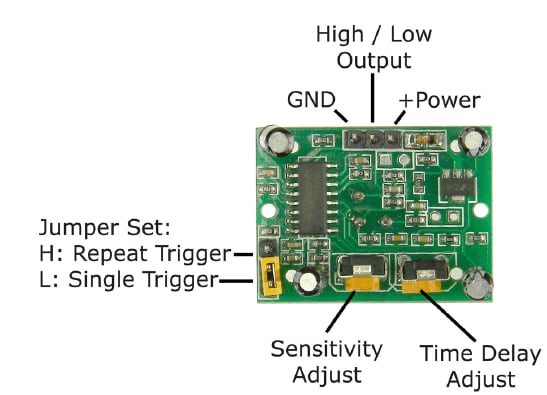
Figure 4. Test jumper and potentiometers
Let's connect the PIR sensor to the Raspberry Pi 5 V, Gnd, and GPIO 24 pins, as shown in Figure 3, and create a Java ME 8 class
HCSR501Device to control it using the Device Access API, as shown in Listing 6.public class HCSR501Device {
private GPIOPin pin = null;
Listing 6.
HCSR501Device class
Then, create a class constructor that initializes and activates the GPIO 24 pin using the
DeviceManager API and the GPIOPinConfigclass (see Listing 7) to establish the following conditions:- Device name: 0
- Pin number: GPIO 24 (specified through
pinGPIO) - Direction: input only
- Mode: pull-down
- Trigger: rising-edge
- Initial value: false
- Wait three seconds before initializing the PIR
public HCSR501Device(int pinGPIO) {
 ...
   pin = (GPIOPin) DeviceManager.open(new GPIOPinConfig(
           0, pinGPIO, GPIOPinConfig.DIR_INPUT_ONLY, GPIOPinConfig.MODE_INPUT_PULL_DOWN,
           GPIOPinConfig.TRIGGER_RISING_EDGE, false));
       I2CUtils.I2Cdelay(3000);    //wait for 3 seconds
  ...
}
Listing 7. Establishing the initial conditions
Now, create a method that receives a defined listener class that supports motion detection events, as shown in Listing 8.
public void setListener(PinListener pirListener) {
...
       if (pin!=null)
          pin.setInputListener(pirListener);
...
}

Listing 8. Method that supports motion detection events
It's also important that you close the pin when you are done, and also make sure you free the pin listener as shown in Listing 9.
public void close() {
...
     if (pin!=null){
          pin.setInputListener(null);
          pin.close();
     }
...
}
Listing 9. Closing the pin and freeing the listener
Let's extend our MIDlet class to support the PIR sensor and its listener, as shown in Listing 10.
//Define HCSR501 Device object
HCSR501Device pir;
private static final int MOTION_DETECTOR_PIN = 24;

@Override
public void startApp() {
...
    //Initialize PIR sensor
    pir = new HCSR501Device(MOTION_DETECTOR_PIN);
    pir.setListener(new PirSensor());
...
}

@Override
public void destroyApp(boolean unconditional) {
...
    pir.close();
...
}

//Check PIR Sensor for motion detection
class PirSensor implements PinListener {

    @Override
    public void valueChanged(PinEvent event) {
        if (event.getValue()) {
            System.out.println("WARNING Motion detected!!!");
        }

    }
}
Listing 10. Extending the MIDlet class to support the PIR sensor and its listener
Connecting the Distance Sensor
The HC-SR04 is an ultrasonic ranging detector that uses sonar to determine the distance to an object much like bats and dolphins do. It comes complete with an ultrasonic transmitter and receiver module and has the following features.
- Power supply: +5 Vdc
- Quiescent current: <2 mA
- Working current: 15 mA
- Effectual angle: <15 degrees
- Ranging distance: 2 cm–400 cm/1 inch–13 feet
- Resolution: 0.3 cm
- Measuring angle: 30 degrees
- Trigger input pulse width: 10 µs
To start a measurement, the HC-SR04 trigger pin must receive a high (5 V) pulse for at least 10 µs, which will initiate the sensor and cause it to transmit eight cycles of ultrasonic bursts at a frequency of 40 KHz and then wait for the receiver to receive the reflected ultrasonic bursts.
When the sensor detects ultrasonic bursts from the receiver, it will set to high (5 V) the echo pin and wait for a period that is in proportion to the distance being measured. To calculate the distance, use the following formula, where "speed of sound in cm/sec" equals 34,029 cm/sec:
Distance = ((Duration in ns of echo pin's high level)*(speed of sound in cm/sec))/ 2 /1000000000 ns
As mentioned earlier, this sensor operates from 5 V, so the trigger pin can be activated by a 3.3 V signal from GPIO 23 with no problem.
In the case of reading the echo signal level, while it is active, the sensor sends 5 V, which is not supported by the maximum Raspberry Pi GPIO 17 pin's voltage, so it is necessary to work with a voltage divider that allows us to convert the signal from 5 V to 3.3 V.
In Figure 5, we see how we can build this voltage divider using two resistors of 330 ohms and 470 ohms to achieve a voltage of 2.9 V at the GPIO 17 pin. You can use this online voltage divider tool to calculate Vout based on the two resistors.
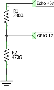
Figure 5. Circuit for the voltage divider
It's time to create a Java ME 8 class called
HCSR04Device to control the HC-SR04 sensor and send a pulse to measure distances in centimeters. See Listing 11.public class HCSR04Device {
private final int PULSE = 10000; // #10 µs pulse = 10,000 ns
private final int SPEEDOFSOUND = 34029; // Speed of sound = 34029 cm/s
private GPIOPin trigger = null;
private GPIOPin echo = null;
Listing 11. Creating the
HCSR04Device class
Now, create a class constructor that initializes and activates the GPIO trigger and echo pins using the
DeviceManager API and theGPIOPinConfig class (see Listing 12) to establish the following conditions:- Device name: 0
- Pin number: trigger = GPIO 23 and echo = GPIO 17 (specified through
_triggerand_echo) - Direction: trigger = output only, echo = input only
- Mode: trigger = output push-pull, echo = input pull-up
- Trigger: none for both
- Initial value: false
- Wait 0.5 seconds before initializing the HC-SR04
public HCSR04Device(int _trigger, int _echo) {
...
trigger = (GPIOPin) DeviceManager.open(new GPIOPinConfig(0, _trigger,
GPIOPinConfig.DIR_OUTPUT_ONLY, GPIOPinConfig.MODE_OUTPUT_PUSH_PULL,
       GPIOPinConfig.TRIGGER_NONE, false));

echo = (GPIOPin) DeviceManager.open(new GPIOPinConfig(0, _echo,
GPIOPinConfig.DIR_INPUT_ONLY, GPIOPinConfig.MODE_INPUT_PULL_UP,
GPIOPinConfig.TRIGGER_NONE, false));

       I2CUtils.I2Cdelay(500);  //wait for 0.5 seconds
 ...
 }
Listing 12. Establishing the initial conditions
The
pulse method calculates the distance in centimeters by setting the trigger pin from 1 to 0 for 10 µs (10,000 ns), and then it computes the time it takes for the echo pin to go from 0 to 1, all in nanoseconds, as shown in Listing 13.public double pulse() {
long distance = 0;
try {
trigger.setValue(true); //Send a pulse trigger; must be 1 and 0 with a 10 µs wait
I2CUtils.I2CdelayNano(0, PULSE);// wait 10 µs
trigger.setValue(false);
long starttime = System.nanoTime(); //ns
long stop = starttime;
long start = starttime;
//echo will go 0 to 1 and need to save time for that. 2 seconds difference
while ((!echo.getValue()) && (start < starttime + 1000000000L * 2)) {
start = System.nanoTime();
}
while ((echo.getValue()) && (stop < starttime + 1000000000L * 2)) {
stop = System.nanoTime();
}
long delta = (stop - start);
distance = delta * SPEEDOFSOUND; // echo from 0 to 1 depending on object distance
} catch (IOException ex) {
Logger.getGlobal().log(Level.WARNING,ex.getMessage());
}
return distance / 2.0 / (1000000000L); // cm/s
}
Listing 13. Method for calculating the distance
Finally, free all resources by closing both pins (see Listing 14).
public void close() {
...
    if ((trigger!=null) && (echo!=null)){
           trigger.close();
        echo.close();;
        }
...
}
Listing 14. Closing both pins
Now, let's extend our MIDlet class to support the HC-SR04 sensor and calculate distances, as shown in Listing 15.
public class TestSensors extends MIDlet {
    //Define HCSR04 Device object
    HCSR04Device hcsr04;
    private static final int TRIGGER_PIN = 23;
    private static final int ECHO_PIN = 17;

    //Define execution of read sensors thread
    private volatile boolean shouldRun = true;
    private ReadSensors sensorsTask;

    @Override
    public void startApp() {
    ...
        //Initialize Ultrasound sensor
        hcsr04=new HCSR04Device(TRIGGER_PIN, ECHO_PIN);
        //Start read sensors data thread
        sensorsTask=new ReadSensors();
        sensorsTask.start();
    }

    @Override
    public void destroyApp(boolean unconditional) {
        shouldRun=false;
    ...
        hcsr04.close();
    }

    // Thread to read distance each 5 seconds
    class ReadSensors extends Thread {
        private double distance=0.0;

        @Override
        public void run() {
            while (shouldRun){
                distance = hcsr04.pulse();
                if (distance>0)
                    System.out.println("Object detected at " + distance + " cm.");
                I2CUtils.I2Cdelay(5000);
            }
        }
    }

}
Listing 15. Extending the MIDlet class to support the HC-SR04 sensor and calculate distances
Before running this MIDlet using NetBeans IDE 8.0, it is important to establish API permissions. To do that, select projectJavaMEDemos, right-click and select Properties to show the Project Properties window, select Application Descriptor, and select theAPI Permissions tab. Include the following four permissions, as shown in Figure 6:
jdk.dio.DeviceMgmtPermission *:* , openjdk.dio.gpio.GPIOPinPermission *:* , open, setdirectionjdk.dio.gpio.GPIOPortPermission *:* , openjava.util.logging.LoggingPermission control, null
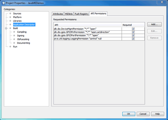
Figure 6. Establishing API permissions
Running the MIDlet in an Emulator Using NetBeans IDE 8
If you do not have a Raspberry Pi but want to test the MIDlet, NetBeans IDE 8.0 has a device emulator that you can create, adapted to a selected pin configuration. In our case we will select the following pin configuration:
- GPIO 17: Input
- GPIO 22: Input
- GPIO 23: Output
- GPIO 24: Input
We will configure the emulator to define these GPIO pins and do our MIDlet tests before uploading Java code to Raspberry Pi.
First, select Tools > Java ME > Custom Device Editor to open the Custom Device Editor window shown in Figure 7.
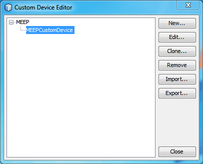
Figure 7. Custom Device Editor window
Select MEEP and then click New to create a new customizable device call MEEPCustomDevice, which is shown in the Edit MEEP Device window shown in Figure 8.
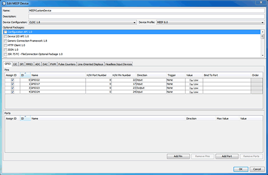
Figure 8. Edit MEEP Device window
In the GPIO tab, create the needed GPIO pins and specify their configuration. When you have finished, click OK.
In NetBeans IDE, you will now see the new device, MEEPCustomDevice, in the Device Selector window.
Install your MIDlet with the device you created by selecting the External Events Generator icon and clicking Install. See Figure 9.
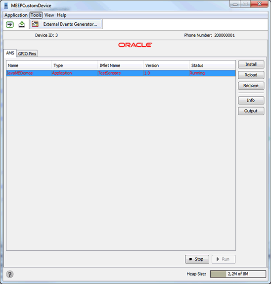
Figure 9. Installing the MIDlet with MEEPCustomDevice
Select the GPIO Pins tab to see all the GPIO pins (Figure 10) that you configured in the Edit MEEP Device window (Figure 8).
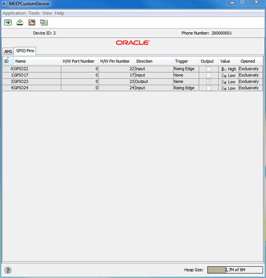
Figure 10. Examining the GPIO pins
Selecting Tools > External Events Generator opens a new window, which is shown in Figure 11. In that window, you can click the buttons for the GPIO 17, GPIO 22, and GPIO 24 pins to emulate a distance sensor, a flame sensor, and a motion sensor, respectively. In addition, at the console you can see a log of the detected events, as shown in Figure 12.
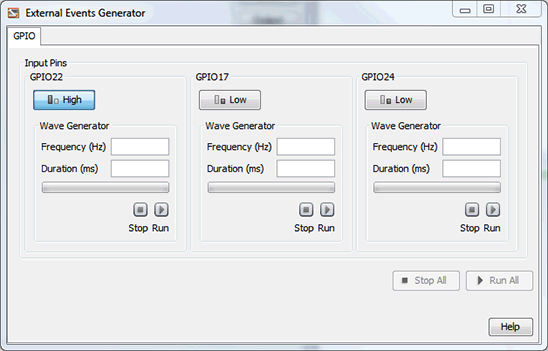
Figure 11. External Events Generator window
Figure 12. Log of the detected events
Conclusion
Each device has its own technical specifications, which must be checked in detail before deciding what type of interface can be connected. In particular, it is important to determine what voltage each device is designed to work with to ensure the life of each device and the Raspberry Pi.
The GPIO interface facilitates the connection of sensors that can be used as either a digital input or a digital output, can be disabled or enabled, and can be used to drive "interrupt" lines. For each device, it is important to define a Java ME 8 class that handles the required transactions and contains suitable control logic, such as the
DFR0076Device, HCSR501Device, and HCSR04Device classes we created for our flame detector, motion detector, and distance sensor devices.
By creating MIDlets, you can easily deploy an application to the Raspberry Pi and do all kinds of experiments, for which only your imagination is the limit. If you don't have a Raspberry Pi but you want to emulate one, NetBeans IDE 8 is a powerful Java integrated development environment that lets you create a virtual device and experiment with interfaces you define.
In the next articles in this series, we will examine other types of sensors—such as sensors that can detect temperature, pressure, and light levels—using other types of interfaces such as I2C, SPI, and UART.
No comments:
Post a Comment